An analysis of the main difficulties associated with foundation excavations adjacent to existing buildings, with insights into ground deformation, subsidence and the risk of structural damage.
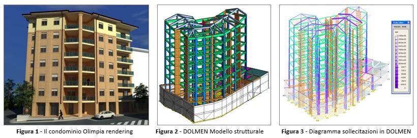
The Olimpia apartment building is located in the city of Acqui Terme, in the province of Alessandria. In total, the building reaches a height of 21.70 m and has 7 floors, including the ground floor, which is intended for commercial and similar activities.
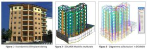
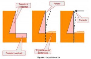
There are also 2 underground levels reaching a depth of 5.95 metres below the building, each with a height of 2.40 m. The structure, designed by Muschiato Ingegneria and modelled with the DOLMEN software produced and developed by CDM DOLMEN Srl, is located next to the overflow channel of the Rio Medrio.
The construction works, which began in autumn 2010 and were completed in autumn 2014, presented considerable difficulties in building the complex, partly due to the hydrogeological conditions of the site.
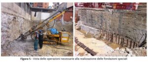
The construction of a building, and in general the removal of a portion of ground, disturbs the state of equilibrium. The ground contains self-balancing horizontal and vertical pressures, and the excavation operation, by removing the portion of ground that locally ensured equilibrium, alters the stress state of the ground, which tends to collapse into the excavation.
In general, therefore, the effect of the excavation is to decompress the ground that was initially in equilibrium and to cause the walls to collapse. To avoid this problem, it is necessary to install a structural element (generally a retaining wall) adequately embedded in the ground below the bottom of the excavation, so as to balance the horizontal pressures. No attention is normally paid to the vertical pressures on the bottom of the excavation, and therefore swelling of the ground occurs. The horizontal pressures act on the retaining wall, which bends, and if the excavation is too deep or the wall is not sufficiently rigid, partial or total collapses and slippages may still occur. The application of shoring at the head of the retaining wall reduces its free span and therefore drastically reduces its stresses and deformations.
Another issue to take into account is that of excavations adjacent to other buildings. The alteration of the stress state, following earth removal around them, is very often a source of damage. The removal of material causes subsidence in nearby structures, due mainly to the nature of the ground; in the case of confined-section excavations in sand, the area subject to subsidence is smaller than its depth. In confined-section excavations in normally consolidated cohesive soils, two types of deformation occur: the first affects the bottom of the trench, with its uplift, and the second involves the side walls of the excavation, with a consequent lowering, in both cases, of the ground surface near the edges. For these soils, the areal extent of the deformation at the sides of the excavation, if the latter is narrow or if a firm lithotype is present at the bottom, is smaller than the depth of the trench. If the thickness of the normally consolidated clay is much greater than the depth of the excavation, or if the latter has a wide section, the lateral area subject to subsidence is far greater than the depth of the trench.
It is also worth remembering that when a rapid excavation is carried out, it is important to consider the presence of water, and not only when it is visible at the excavation face, because it is well known that it is not so much the flow rate of the seeping water that compromises the stability of the ground walls, but rather the distribution of the pore pressures caused, in particular, by the excavation itself. In cohesive soils where no water inflows are encountered, pore pressures can generate strong deformations around the excavation, only sometimes a forewarning of collapse.
Given the numerous problems involved in building a structure bordering existing properties, it was decided to carry out the foundations in different phases, gradually addressing the difficulties already identified at the preliminary stage.
In order to provide a reconstruction of the construction subsoil, 2 continuous dynamic penetration tests were carried out to test the compactness characteristics of the horizons overlying the in-situ rocky substrate. Test P1, carried out near the entrance gate, found a first level with low compactness characteristics, represented by silty alluvial deposits and fine sandy silts extending from the ground surface down to a depth of 3.80 m. Below this is a horizon with good compactness characteristics and a high degree of compaction down to -4.70 m, the depth at which the test ended due to the refusal of the driving device to advance.
Test P2, carried out in the centre of the area under examination, found a strong similarity to the previous one.
To solve the main problem, namely the risk of the stream flooding, it was necessary to excavate 6 metres below ground level, that is, 2 m more than where the overflow channel is located, and to seal any water leaks, so as not to risk any ground subsidence.
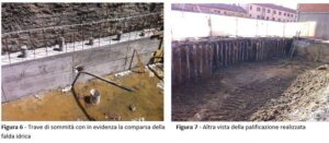
The retaining structure that made it possible to carry out the excavation and the subsequent foundations is a micropile retaining wall, for which the retaining function is ensured mainly by the resistance of the volume of ground in front of the structure and by two rows of temporary active tie-rods.
The retaining wall in question has the following characteristics:
To strengthen the stability of the building, support beams were driven in at the base, penetrating the ground, from which tie-rods extend that diagonally pierce the subsoil, ensuring an even distribution of the structure's weight at the base. The foundations are also placed lower, not only than the Medrio overflow channel but also than the neighbouring building, in order to wedge the building between the two spaces and make it as solid and as unobtrusive as possible.
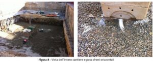
The other problem that arose concerned the appearance of the water table.
To overcome this drawback, surface drainage works were carried out: these are intended to limit surface runoff and the consequent erosion, keeping the surrounding hydraulic conditions under control.
Subsequently, the layer of lean concrete was laid and the raft reinforcement and casting were positioned.
Puoi scegliere di impedire a questo sito web di aggregare e analizzare le azioni che intraprendi qui. Ciò proteggerà la tua privacy, ma impedirà al proprietario di imparare dalle tue azioni e di creare un'esperienza migliore per te e per gli altri utenti.
You may choose to prevent this website from aggregating and analyzing the actions you take here. Doing so will protect your privacy, but will also prevent the owner from learning from your actions and creating a better experience for you and other users.