The use of reinforced earth for the restoration of a collapsed slope: the reasons for the choice, the design principles and the modelling
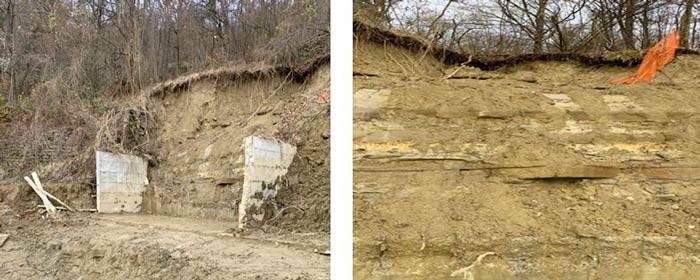
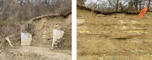
Figura 1 - Immagini dopo l’evento franoso
Following a landslide event in a locality in southern Piedmont, it became urgent to intervene to make the collapsed slope safe, at the foot of which there was also a residential building under construction. The solution chosen to stabilise the slope was that of reinforced earth. This article analyses the reasons for this choice, the design, and the modelling aspects carried out using the IS GeoPendii software.
In November 2019, in a locality in southern Piedmont, in a hilly area between the Apennines and the Langhe, intense rainfall lasting several days triggered landslide phenomena on the slope located in that same locality, which had already been compromised by weather events in the preceding months. The landslide, of the sliding type, developed over a front of about 20 linear metres in a conical shape, with a height varying from 6 to 7 linear metres and a depth of about 11 linear metres; it caused the detachment of the edge of a terrace, composed of colluvial material resting on a rock bank, which in turn consisted of alternating layers of sandstone, poorly cemented sand and over-consolidated claystone. The landslide event also dragged with it medium-sized rock material, which destroyed part of a retaining wall located there, which had become unfit to withstand a thrust of high intensity.
The danger of the event, which threatened to compromise the integrity of a residential building under construction located at the foot of the collapsed slope, required immediate intervention to develop a project aimed at restoring, stabilising and, of course, making safe the affected slope.
This project was entrusted to Eng. Pierluigi Muschiato, owner of Studio Muschiato Ingegneria, who, having assessed the critical aspects of the project and, above all, of the work area, decided to adopt the use of reinforced earth as the technique for reconstituting the slope — a solution that today undoubtedly represents a valid alternative to traditional slope stabilisation techniques, both as regards the economic side and that of aesthetics, sustainability and environmental integration, an aspect that has become one of the indispensable cornerstones of the engineering profession.
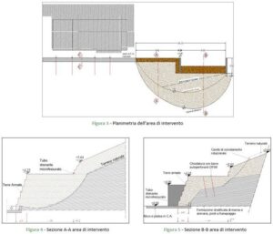
The slope was therefore reconstructed using reinforced earth arranged on two different levels, the first from a level of +0.00 m to +4.25 m, the second from +4.25 m to 5.55 m, also paying particular attention to the removal of water from the landslide body, necessary both during the execution phase of the work and after its completion, in order to avoid future landslide events caused by the establishment of water circulation over the rocks and in the fractures, with the consequent formation of sliding surfaces.
The drainage of rainwater and its surface management were carried out by shaping the surface of the slope in order to bring the non-horizontal surfaces to a gradient angle compatible with the nature of the material used to manage the rainwater. The runoff of the water was instead diverted through the rapid growth of the grass cover and the subsequent planting of species native to the area.
At the rear of the dwelling located there, a drainage channel will be built to collect the surface runoff water and that deriving from the rocks. As regards the drainage of the soil accumulations and the reinforced earth walls, micro-slotted Φ 100 mm pipes will be fixed to them on two different planes.
The design choice to intervene by means of reinforced earth, a technique well known in the literature of naturalistic engineering, immediately became indispensable for several reasons: firstly, the difficult accessibility of the project area and, secondly, the consequent need to reduce the movement of material from outside the work area. The area to be stabilised, being surrounded by woodland and characterised by particularly steep slopes, made it difficult to reach by large work vehicles, which would have been necessary for any other type of intervention. As regards the movement of material from outside the work area, this aspect was resolved through the recovery and reuse of the landslide material.
Reinforced earth is essentially made up of two materials: the earth and the reinforcement; the former essentially plays the role of concrete, that is, it is characterised by good compressive strength, while the latter compensates for the soil's poor capacity to resist tension.
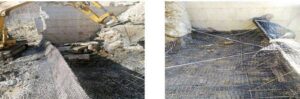
In this specific case, the situation allowed the total reuse of the landslide material, consisting of colluvial earth and rocks, which together with the geosynthetic reinforcements (known as geogrids), inserted in successive layers horizontally within the soil, allowed the development, through friction, of a tangential stress state, which in turn allowed the composite system to withstand stress levels far higher than those possible with the solid matrix (soil) alone. Reinforced earth is also known as a vegetated structure and therefore allows complete environmental integration, ensured also by the grassing of the front and the subsequent planting of species native to the area, which, as well as providing aesthetic prominence by maintaining the integrity of the surrounding landscape, helps to protect the front face from erosive action and provides greater support.
No less important is the aspect related to the speed of construction of the work; indeed, despite the difficulties encountered in the particularly rugged work area, the rapidity of the intervention made it possible to safeguard the area and the neighbouring dwelling under construction in record time. This aspect, combined with the possibility of using materials sourced locally and others at advantageous costs, such as the geogrids and the geomats or biotextiles adopted to facilitate revegetation, ensures a worthwhile economic saving. Technical characteristics such as the following are also undoubtedly an added value:
The spread of reinforced earth over the last thirty years is therefore not the result of chance, but a sign of a new design awareness which, while not forgetting the functional, economic and above all safety and stability aspects of the work, mobilises to respect the surrounding environment, to maintain and enrich it without distorting it.
Also worth mentioning is the method of calculation and structural modelling that was chosen, carried out with the aid of DOLMEN, a calculation software of proven reliability that makes it possible to perform a detailed analysis of geotechnical and structural behaviour.
In particular, the IS GeoPendii software was used, which studies the stability analysis of slopes based on limit equilibrium methods, allowing the insertion of the specific intervention that was decided upon for the slope itself, in this case the reinforced earth.
Reinforced earth structures are retaining works to all intents and purposes and, as such, are covered by the NTC 2018 Technical Standards for Construction, incorporated into the DOLMEN software so that they can be used both in the static calculation with design approach 1 (which was chosen) and for the seismic slope-stability calculation, also carried out in accordance with the provisions of the Technical Standards, in particular paragraph 7.11.3.5.2, that is, by applying an equivalent pseudo-static action proportional to the weight of the volume of partially unstable soil.
Reinforced earth structures are subject in particular to external, internal and compound checks. The external checks concern the work considered as monolithic (a rigid retaining structure), and consist of sliding along the base, overturning at the toe, and bearing capacity.
The internal checks concern the verification of the monolithic nature of the work itself, isolated from the slope, and consist of direct sliding along a level of reinforcements and of the tensile and pull-out resistance of the reinforcements, and are conducted as set out below.
Finally, the compound checks are carried out by considering the contribution that each reinforced-earth layer makes to overall stability, considered as an integral part of the slope.
The principles followed in the calculation, as anticipated earlier, refer to the well-established limit equilibrium method, in which, within a very extensive slope subjected to plane deformation, a volume is isolated by means of a cylindrical surface. The soil is in limit equilibrium when the failure condition is satisfied, which, under the Mohr-Coulomb criterion, is a function of cohesion, the angle of shear resistance and the pore pressure. If along the surface the applied shear stress, known as the mobilised resistance, is less than the available failure resistance, a limit equilibrium condition can be determined by means of a safety factor, which represents the factor by which to divide the soil's resistance parameters in order to obtain failure of the slope along the surface considered. This value is assumed to determine the safety of the slope against shear failure and is taken as constant along the entire surface, so that at every point on it the same proportion of shear resistance is mobilised. It follows that the safety factor is given by the ratio between the available resistance and the mobilised resistance. To determine this value, the equations of equilibrium of rigid bodies are used, that is, the equations of equilibrium for horizontal and vertical translation and for rotation about a point in the plane of the forces. A large number of surfaces is defined within the slope, and a safety factor can be associated with each of these. The lowest safety factor defines the so-called critical surface and is taken as representative of the slope's stability conditions. Within the theory of limit equilibrium, numerous methods have been developed for calculating the safety factor; among these are the so-called methods of slices, which involve dividing the volume of soil considered into blocks of finite but small thickness, for which the equilibrium equations can be written. With these methods, it is possible to consider slopes of complex shape made up of soils with different physical and mechanical characteristics. To keep the slices in equilibrium, the resultants of the effective stresses and the pore pressures, which are mutually transmitted between the blocks, must be applied to the sides and the base. The possible failure surfaces are thus generated within the calculation and, among all the sliding surfaces produced, only the failure surface known as critical — that is, the one with the lowest stability factor — will be chosen within the various calculation methodologies.
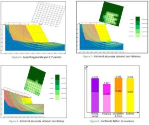
Below is the image taken directly from the DOLMEN software showing the failure surfaces generated within the slope through the various methods adopted and implemented by IS GeoPendii, including the Bishop method, the Fellenius method, the GLE/Morgenstern-Price method and, finally, the Spencer method, used for the two different slopes into which it was decided to divide the slope for calculation purposes. Once the critical surface has been identified, the division into slices mentioned earlier is carried out in order to assign the appropriate critical safety factor.
At the end of the calculation, developed using various methods, it was possible to compare them and produce a comparison between the different safety factors calculated; the result obtained was positive, that is, the checks were satisfied according to all the theories applied.
Puoi scegliere di impedire a questo sito web di aggregare e analizzare le azioni che intraprendi qui. Ciò proteggerà la tua privacy, ma impedirà al proprietario di imparare dalle tue azioni e di creare un'esperienza migliore per te e per gli altri utenti.
You may choose to prevent this website from aggregating and analyzing the actions you take here. Doing so will protect your privacy, but will also prevent the owner from learning from your actions and creating a better experience for you and other users.